Cómo Construir un Reloj WiFi con Arduino Uno R4 WiFi, Módulo RTC y Pantalla LCD
Introducción
En esta guía, aprenderemos a construir un reloj conectado a WiFi usando un Arduino Uno R4 WiFi, un módulo RTC y una pantalla LCD. Este reloj sincronizará la hora con un servidor NTP y la mostrará en una pantalla LCD, actualizándose cada segundo. Este proyecto combina la electrónica y la programación, siendo ideal tanto para principiantes como para aquellos con más experiencia.

Componentes Necesarios
Para este proyecto, necesitaremos los siguientes componentes:
- Arduino Uno R4 WiFi
- Módulo RTC (RTC8563)
- Pantalla LCD con retroiluminación RGB (Grove)
- Cables puente
- Protoboard (opcional)
- Cable USB-C
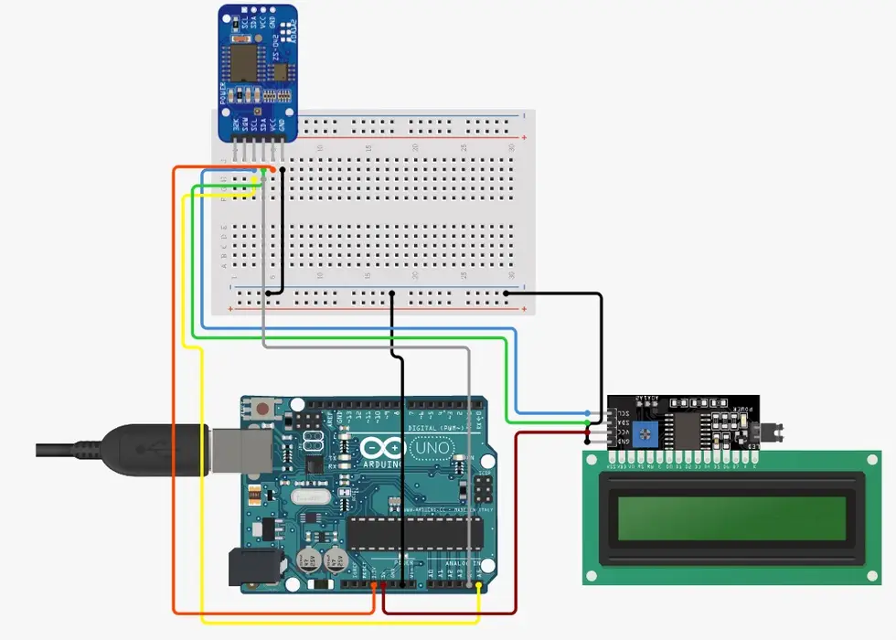
Paso 1: Conexión del Hardware
- Conectar el Módulo RTC y la Pantalla LCD al Arduino:
- Conecta el pin VCC del RTC al pin 5V del Arduino.
- Conecta el pin GND del RTC al pin GND del Arduino.
- Conecta el pin SDA del RTC al pin SDA del Arduino.
- Conecta el pin SCL del RTC al pin SCL del Arduino.
- Conecta el pin VCC de la pantalla LCD al pin 5V del Arduino.
- Conecta el pin GND de la pantalla LCD al pin GND del Arduino.
- Conecta el pin SDA de la pantalla LCD al pin SDA del Arduino.
- Conecta el pin SCL de la pantalla LCD al pin SCL del Arduino.
Paso 2: Configuración del Software (Parte 1)
Preparación del Entorno de Desarrollo:
Abre el IDE de Arduino.
Instala las bibliotecas necesarias desde el gestor de bibliotecas:
- RTC
- WiFi
- Cliente NTP
- RGB_LCD
Paso 3: Configuración del Software (Parte 2)
Carga del Código:
Abre el código en el IDE de Arduino.
Asegúrate de modificar la zona horaria y los detalles de la red WiFi en el código según tus necesidades.
Paso 4: Cargar el Código y Ponerlo en Marcha
Carga y Verificación:
Conecta el Arduino a tu computadora usando un cable USB-C.
En el IDE de Arduino, selecciona la placa y el puerto correctos.
Haz clic en el botón de carga para transferir el código al Arduino.
Abre el Monitor Serial para verificar el estado de la conexión WiFi.
Observa la pantalla LCD para confirmar que muestra la hora correcta.
					#include <Wire.h>
#include <RTClib.h>
#include <WiFi.h>
#include <NTPClient.h>
#include <WiFiUdp.h>
#include "rgb_lcd.h"

// Define RTC
RTC_PCF8563 rtc;

// Initialize the Grove LCD RGB Backlight library
rgb_lcd lcd;

// WiFi credentials
const char* ssid = "your_ssid";
const char* password = "your_password";

// NTP client setup
WiFiUDP ntpUDP;
const long utcOffsetInSeconds = 2 * 3600; // This is to adjust for the timezone (For me, it's UTC+2)
NTPClient timeClient(ntpUDP, "pool.ntp.org", utcOffsetInSeconds, 60000); // Update interval: 60s

void setup()
{
    // Here we initialize the Serial Monitor for debugging purposes
    Serial.begin(9600);

    // Here we initialize the RTC module
    if (!rtc.begin())
    {
        Serial.println("Couldn't find RTC");
        while (1);
    }

    // In this part, we initialize the LCD and set the backlight color to white
    lcd.begin(16, 2); // Specify the number of columns and rows
    lcd.setRGB(255, 255, 255); // Set backlight color to white

    // Here we display "Hello world" on the first line and "Hello world 2" on the second line to verify LCD functionality
    lcd.setCursor(0, 0); // Set the cursor to column 0, line 0
    lcd.print("Hello world");
    lcd.setCursor(4, 1);
    lcd.print("Hello world 2");
    delay(2000); // Wait for 2 seconds to see the message

    // Here we clear the LCD display
    lcd.clear();

    // In this part, we initialize the WiFi connection
    WiFi.begin(ssid, password);
    int wifiAttempt = 0;
    while (WiFi.status() != WL_CONNECTED && wifiAttempt < 3)
    {
        delay(1000);
        Serial.print(".");
        wifiAttempt++;
    }

    // Here we check if the WiFi connection was successful
    if (WiFi.status() == WL_CONNECTED)
    {
        Serial.println("Connected to WiFi");
    }
    else
    {
        Serial.println("Failed to connect to WiFi");
    }

    // Here we initialize the NTP client to get the time
    timeClient.begin();

    // Here we display the initial time on the LCD
    displayTime();
}

void loop()
{
    // In this part, we update the RTC from the NTP server if WiFi is connected
    if (WiFi.status() == WL_CONNECTED)
    {
        timeClient.update();
        updateRTC();
    }

    // Here we update the time display on the LCD
    displayTime();
    delay(1000); // Refresh the display every second
}

void updateRTC()
{
    // What we're doing here is updating the RTC with the current time from the NTP server
    if (timeClient.update())
    {
        unsigned long epochTime = timeClient.getEpochTime();
        DateTime now = DateTime(epochTime);
        rtc.adjust(now);
    }
}

void displayTime()
{
    DateTime now = rtc.now();

    // Here we clear the previous display content on the LCD
    lcd.clear();

    // What we're doing here is displaying the connection status on the first line
    if (WiFi.status() == WL_CONNECTED)
    {
        lcd.setCursor(3, 0); // Center "Clock C" on the first line
        lcd.print("Clock C");
    }
    else
    {
        lcd.setCursor(3, 0); // Center "Clock D" on the first line
        lcd.print("Clock D");
    }

    // In this part, we display the current time on the second line
    lcd.setCursor(4, 1); // Center the time on the second line
    lcd.print(now.hour() < 10 ? "0" : ""); // Leading zero for single digit hour
    lcd.print(now.hour(), DEC);
    lcd.print(':');
    lcd.print(now.minute() < 10 ? "0" : ""); // Leading zero for single digit minute
    lcd.print(now.minute(), DEC);
    lcd.print(':');
    lcd.print(now.second() < 10 ? "0" : ""); // Leading zero for single digit second
    lcd.print(now.second(), DEC);
}
Esquema de conexion